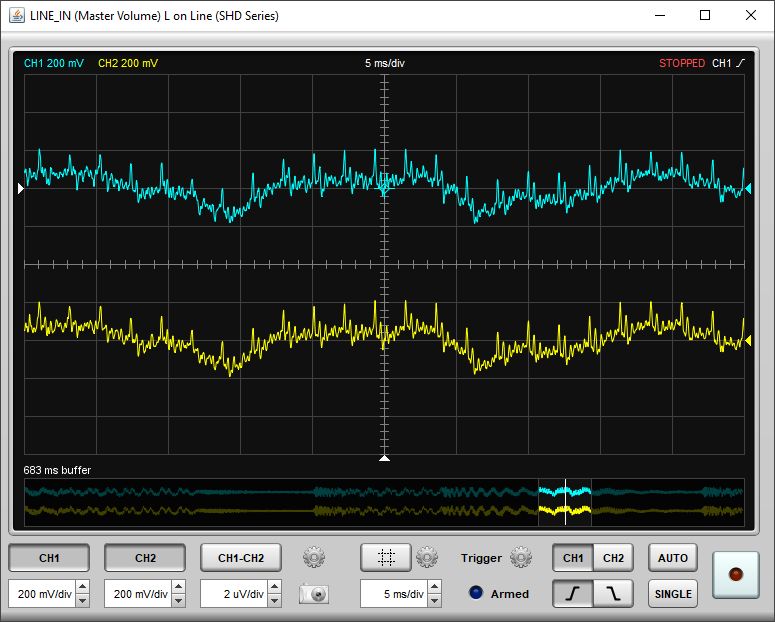
The Scope emulates a two channel oscilloscope with an additional math channel. It provides a live view of the audio data on the measurement and reference channels. The channels are colour coded, blue for CH1 (the measurement channel), yellow for CH2 (the reference channel) and green for the math channel. REW captures input data in blocks of 8k samples, so the scope receives blocks of samples at a time which makes it behave a little differently to a hardware scope.
The top of the screen shows the currently selected channels, their voltage
scale, the timebase and the trigger settings.
The bottom of the screen shows the capture buffer, with the currently
displayed portion highlighted. The position of the trigger is shown as white
line. When the scope is stopped the highlighted portion can be dragged to
change the region displayed in the main scope area. For finer control of the
displayed region the main display can be dragged by clicking and dragging it.

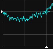
The trigger level and position are shown by white triangles at the left
and bottom of the display. They can be adjusted by clicking on them and dragging
them to the desired position. The trigger position is shown on the trace by
a crosshair symbol.
The control panel has channel selectors and voltage scale controls for
each channel, a screen capture button, a button to turn cursors on and off,
the timebase control, trigger controls and a button to start and stop capture.
The timebase can also be adjusted using the mouse wheel when the cursor is in
the display area.

Next to the channel selects is a button (cog icon) for channel settings,
including the channel offsets, input scaling (defined by the rms voltage
of a full scale sine wave on each measurement channel), full scale lines,
persistence, math function and data export. Offsets can be reset to zero using the Reset
buttons. The zero volts position for each trace is shown as a triangle in the
trace colour on the right of the display. The vertical offsets can be adjusted using the
channel settings controls or by clicking and dragging on the offset indicators on
the right hand side of the display. The horizontal offset controls will shift the traces
by the number of samples corresponding to the offset at the current timebase. DC
offsets are added to the trace data values.
If Full scale lines is selected dotted lines will be drawn at the voltages
corresponding to positive and negative full scale for each input channel. The persistence
setting emulates analog persistence, with the last 10 sweeps shown progressively
more faintly.
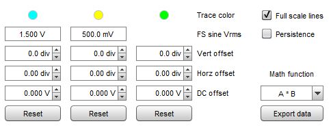
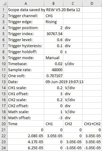
Export data writes the scope data and its settings to a
text file using the delimiter set in the File → Export menu. The image below
shows a file exported as .csv and loaded into a spreadsheet. Note that data is
exported at the captured sample rate as normalised float sample values, where
1.0 is full scale. The sample value corresponding to one volt for each channel is
included in the header information.
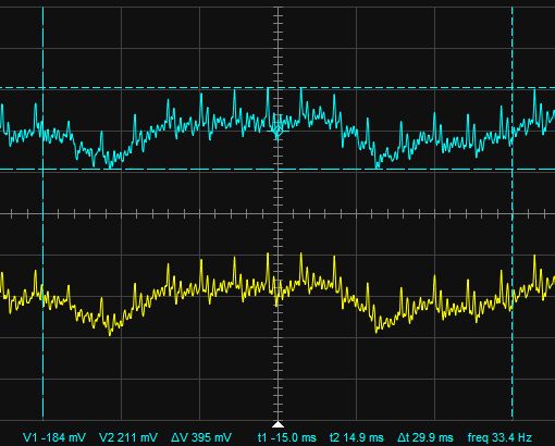
The cursor button shows or hides the scope cursors. The settings icon next to the button brings up a menu to control the cursor operation. There are two cursor modes, Manual and Tracking, In both modes the readings for the cursors are shown below the graph. Times are relative to the trigger position, which is t=0.
Manual mode provides two time cursors and two voltage cursors. Either or both sets can be shown according to the settings selection. The channel selection determines which channel the voltage cursors are referenced to. Cursors are drawn in the colour of the selected channel. Each pair of cursors has a primary cursor (1, long dashes) and a secondary cursor (2, short dashes). When the primary cursor is moved the secondary moves with it, the secondary cursor can be moved independently. Cursors are moved by clicking and dragging them.
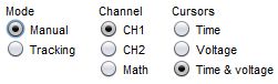
Tracking mode provides two time cursors which can be adjusted and two voltage cursors which track the selected channel. The cursors can show readings from the same channel or from separate channels according to the settings.
![]()
![]()
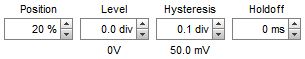
The scope can be triggered on channel 1 or channel 2, rising or falling edge.
The trigger level, hysteresis and holdoff can be adjusted in the trigger settings
menu. They can also be adjusted by clicking and dragging on the trigger indicators.
When dragging the trigger level the hysteresis can be adjusted using the mouse wheel.
In AUTO mode the scope will sweep automatically if a trigger has not been
detected within the span of the display. In SINGLE the scope will wait
for a trigger and stop capture after a single sweep.