The Thiele-Small Parameters window is used to calculate the parameters
for a drive unit from measurements of its impedance. Three methods are
offered: sealed box, added mass and dual added mass. The dual added mass
method if from the paper "An Added-Mass Measurement Technique for Transducer
Parameter Estimation" by Jeff Candy and Claus Futtrup, JAES Volume 65 Issue
12 pp. 1005-1016; December 2017. It gives the most accurate results, but all
the methods are dependent on the quality of the measurements.
Each method requires a "free air" measurement, with the driver rigidly supported, without any baffle, and mounted vertically (i.e. so that the cone is firing horizontally as it would be in a typical loudspeaker installation). Additional measurements are with either mass added to the cone or with the unit in a sealed (air tight!) enclosure (ideally with a volume a little less than the expected Vas).
For single added mass measurements the mass added should be approximately half the expected Mms figure. For dual added mass make one measurement with masses that total a little less than the expected Mms, then one with half the masses removed, then finally the free air measurement. Some pre-conditioning of the unit with signals at medium levels helps to stabilise the behaviour and suspension compliance and reduce memory effects in the suspension from periods of storage or lack of use. Quiet conditions are important for good measurements, drive units act as microphones and pick up noise and vibration, affecting the results. The measurements should be made up to 20kHz so that the lossy inductance of the voice coil can be accurately modelled, and the impedance calibration step should be carried out before making measurements.
Added mass measurements require very precise figures for the masses to get accurate results. The more accurate the scale used, the better. It is recommended that the overall mass to be added is split into 4 pieces, of approximately equal mass, placed equally spaced around the cone near the voice coil and firmly attached. Blu-tack works well, either on its own or with a nut embedded in it when more mass is required. Do not place the masses near the outer edge of the cone, that will adversely affect the cone behaviour. For the second measurement in a dual added mass run a pair of the masses are (gently!) removed, leaving two on opposite sides of the cone.
Compensate for leakage losses and Compensate for Air Load check boxes are shown for sealed box measurements, they take into account the leakage loss of the sealed box (which would be shown as Ql in the results) and the air mass load due to the sealed box. These compensations use the Carrion-Isbert method described by Claus Futtrup in the documentation for his Driver Parameter Calculator application at http://www.cfuttrup.com/
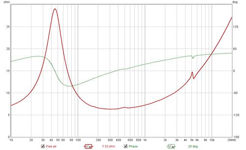
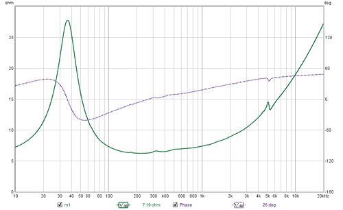
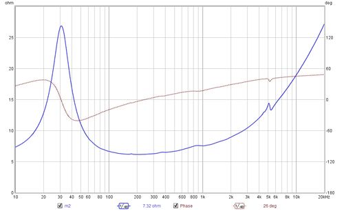
The results show the process for TS parameter calculation of a mid-bass drive unit. The plots below show the impedance measurements made in free air and then with the added masses. A least squares fit of an electrical model of the drive unit impedance is carried out on the free air measurement to determine the model parameters. Another least squares fit is carried out on the secondary measurement to determine the modified motional parameters and the TS parameters are then calculated.
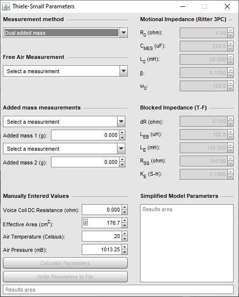
To calculate the TS parameters the measurements are selected and the required values are entered:
The Calculate Parameters button is then clicked, with the following results.
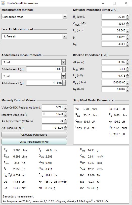
The first column of results in the bottom of the window show the loudspeaker resistance RE, which is generally a little higher than the DC resistance; the minimum impedance Zmin after the peak and the frequency fmin at which it occurs; f3, which is the frequency at which the impedance has increased to sqrt(2)*Zfmin; the inductance at f3; the effective diameter and the effective area. The second column shows the resonant frequency fS; the mechanical (QMS), electrical (QES) and total (QTS) Q-factors and the FTS figure (fS/QTS). These parameters can also be calculated for any single measurement, without requiring a secondary measurement to be selected. The LP figure and the MMS, CMS, RMS, VAS, Bℓ and Eta (efficiency) figures in the third column can only be calculated using extra measurements.
The results can be copied to the clipboard by right-clicking on the results area, or written to a text file using the Write Parameters to File button. When writing to file the separator between values, labels etc is as defined in the File → Export menu.
The plot below shows the modelled impedance traces overlaying the measured values for the free air measurement.
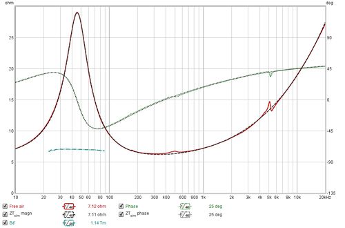
Dual added mass measurements include a Bℓ curve (cyan in the image), it should be close to horizontal around the resonant frequency if the measurements are good.
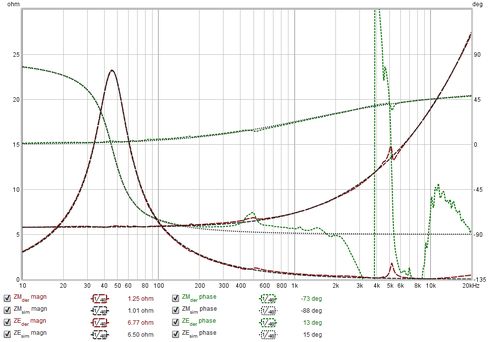
When TS parameters have been calculated the derived and simulated motional and blocked impedance magnitudes and phases can be plotted in addition to the total impedance traces, along with the ZM* magnitude and phase for dual added mass results. The simulated traces are produced using the model parameter values, the derived traces are produced by subtracting the model values from the measured values (for example, derived motional impedance is produced by subtracting the modelled blocked impedance from the total measured impedance).
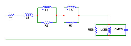
REW uses a model for the electrical impedance component of the driver based on "Electrodynamic Transducer Model Incorporating Semi-Inductance and Means for Shorting AC Magnetization" by Knud Thorborg and Claus Futtrup, JAES Volume 59 Issue 9 pp. 612-627; September 2011. The diagram below shows the components of the electrical impedance model.
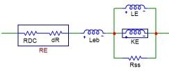
The model begins with a drive unit resistance RE which is the DC resistance RDC. REW has an additional resistance dR which allows for the difference between the actual RE and the measured resistance, which may differ due to measurement errors or coil temperature. It is followed by a series inductance LEB and then a parallel combination of an inductance LE, a semi-inductance KE and a resistance RSS. LE represents the inductance of the part of the voice coil located inside the motor gap. LEB represents the part of the coil outside the motor gap. The semi-inductance KE has an impedance that varies with the square root of omega. It models the effects of eddy currents and skin depth in the pole piece. The parallel combination of LE and KE models the transition of the coil's behaviour from largely that of a conventional inductor at low frequencies to a semi-inductor at high frequencies. The RSS component models the effect of electrically conductive material in the magnet system. The parameter values REW determines may be modified if desired and the effect on the modelled impedance and phase traces viewed on the graph, but the TS parameters which have been calculated will not be altered.
The mechanical impedance model incorporates elements that cater for the frequency-dependence of compliance. It uses the LOG model of viscoelasticity, from "Low-Frequency Loudspeaker Models That Include Suspension Creep" by Knudsen and Jensen, JAES Volume 41 Issue 1/2 pp. 3-18; February 1993, with the added Retardation Spectra function as described in "Modeling Viscoelasticity of Loudspeaker Suspensions Using Retardation Spectra" by Agerkvist and Ritter, AES Convention: 129 (November 2010), Paper Number: 8217.
As frequency-dependent component values are not supported by many circuit simulators REW also calculates values for an alternative blocked impedance model using two parallel resistor-inductor pairs in series, labelled R2-L2 and R3-L3, and the conventional RES, CMES, LCES motional impedance model without the frequency-dependent damping and compliance. The values of these components are shown in the "Simplified Model" box. This diagram shows the simplified model components.