The Soundcard Preferences panel is used to configure the audio input and output
used for measurement, calibrate the audio interface and establish the correct
levels for making measurements.
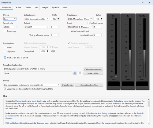
The various controls on the panel are as follows:
- Drivers
- On Windows platforms there is a choice of Java or ASIO drivers for
the audio interface. The Java drivers support 44.1, 48, 88.2, 96 and 192 kHz sample
rates and 16-bit data. On macOS and Linux 32-bit or 24-bit data is used if the interface offers
it. Java drivers permit the input and output to be on different devices and allow volume
control from REW.
The ASIO drivers support up to 1536 kHz and a variety of formats depending on the driver.
ASIO drivers support one ASIO device which must be used for both input and output
and REW has no control over levels. Pseudo-ASIO drivers such as ASIO4All create an
ASIO wrapper around the WDM drivers for devices, allowing input and output through
different devices.
- Sample Rate
- With Java drivers the sample rate may be set to 44.1, 48, 88.2, 96 or 192 kHz,
the default is 48kHz. To prevent resampling in the OS make sure the audio interface
is configured to operate at the sample rate selected in REW. With ASIO drivers the
choice of sample rates offered will reflect those the interface supports, with a
maximum sample rate of 1536 kHz. Note that the lists of input and output devices only
include those devices that report they support the selected sample rate, if your device
does not appear in the lists try changing the sample rate.
- Stereo only
- Java drivers can be restricted to requesting stereo connections to the audio
interface by selecting Stereo only.
- Inputs and Outputs (Java drivers)
- The input and output device lists show the physical devices that
Java has found that report they support the selected sample rate, along
with some OS virtual devices. The lists of inputs and outputs are specific
to the selected input device and output device. The
Default Device settings tell REW to request
the defaults that have been set in your OS (in the Sounds and Audio Devices
control under Windows or the Audio and Midi Setup utility under macOS).
When the default devices have been selected REW leaves all control of
the audio inputs and outputs and their associated volume controls
to you, use the controls provided by your interface's mixer or OS controls
to set levels and select inputs and outputs as required. Note that
when using a USB mic with a cal file that contains a sensitivity figure
REW needs to read the input volume setting to correctly show SPL, to allow
that the input device and input for the mic must be selected (they must not
be left as "Default Device").
- Output Channel (Java drivers)
- REW can place its test signals on either or both of the output channels.
If there are more than 2 available output channels the first and second can be driven
at the same time - which channels those are can be configured using the
Output Channel Mapping dialog (see below). The output channel selection can
also be made directly on the measurement panel or signal generator.
- Timing Reference Output Channel (Java drivers)
- When using a timing reference the output channel will be the channel selected here.
The selection can also be made directly on the measurement panel.
- Output Mapping (Java drivers)
- On some platforms Java supports multichannel output - currently Windows does not
offer this unless using the Wasapi Exclusive (EXCL) entries. If the platform supports
multichannel and the current output has more than 2 channels an output channel mapping
button is shown:
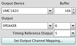
The button brings up a dialog to select up to 17 channels for use while measuring:
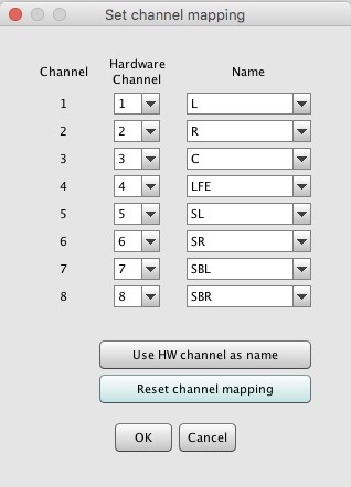
Each of the channels can be assigned to any of the available hardware outputs. They can
be labelled with surround channel names, or the hardware channel number, or the
output number.
- Input Channel (Java drivers)
- REW only uses one interface channel to capture the output of your
SPL meter or mic preamp, the Input Channel
control tells REW which channel you have connected to. The default is
the Right channel. If Use loopback as timing reference
has been selected in the Analysis Preferences the
other channel will be used a reference to eliminate time delays within the
computer and interface, this requires a loopback connection on the reference
channel.
- Input options
- If the interface (or something else in the input chain) inverts its input
select the Invert checkbox to restore correct polarity.
If the input has a DC offset check the High Pass box to
have REW apply a 2 Hz high pass filter.
- Loopback Input Channel (Java drivers)
- When the input is stereo the loopback defaults to the channel not being used
for measurement. If multiple input channels are available the input to use for the
loopback can be configured here.
- Virtual balanced input
- If this option is selected a Balanced input selection is offered. The
balanced input will be subtracted
from the measurement input and the result scaled by 0.5. This simulates the behaviour
of a balanced input, and is appropriate if the balanced input is driven by an inverted
signal (such as by selecting the Invert second output option on the signal
generator).
- Volume Controls (Java drivers)
- The Output and Input volume controls are only enabled if you
have selected specific input and output devices, have checked the
boxes to allow REW to Control output volume
and Control input volume and REW
has been able to obtain controls for the selected devices from the OS.
Under those conditions REW will set the volume controls to the levels
last used for measurement and select the chosen input. These controls
are not enabled on macOS, macOS only permits values corresponding to
specific dB increments which vary according to the device and its volume
range. Use Audio MIDI Setup to control volume settings on macOS.
- Sweep Level
- The Sweep Level control sets the RMS level
at which REW will generate its measurement sweep, relative to digital
full scale. The highest level possible is -3 dBFS, unless the
View preference Full scale sine rms is 0 dBFS
has been selected, in which case the maximum is 0 dBFS. Using the maximum
value places the peaks of the signal at digital full scale. A typical
setting is -12 dBFS (the default). This selection can also be made directly
on the measurement panel.
- Output Buffer, Input Buffer (Java drivers)
- The Output Buffer and
Input Buffer controls set the size of the
buffers used when accessing the interface. The default settings are 32k
(meaning the buffer sizes are 32,768 pairs of audio samples). If you
experience occasional glitches or interruptions in the signal generator
output try increasing the replay buffer size, but note that there are other
possible causes of this, such as interference from wireless cards.
Similarly if the captured audio signals (as shown in the Scope graph panel)
have occasional dropouts try increasing the record buffer. Using larger
buffers will increase latency (delays when starting and stopping replay
and recording) but should otherwise not be detrimental. If you are not
experiencing any problems with audio input or output you may wish to
reduce the buffer sizes to minimise latency.
- Treat 32-bit data as 24-bit
- 32-bit integer sample formats often carry 24-bit data. Treating them as
32-bit data generates low level harmonic artefacts (at around -160 dBFS), to
prevent that they should be treated as 24-bit samples. If a device is genuinely
32-bit turning this option off will provide the full resolution of the device,
but note that REW uses 32-bit float to distribute audio data internally which means
the effective integer-equivalent dynamic range is 25 bits.
- Calibration Panel
- The controls in the Calibration
panel are used to calibrate the interface.
The browse
button is used to select a calibration file, a plain text file which by default
has the extension .cal, though other extensions are also accepted. The
file format is detailed below. The delete button
clears the calibration data structures, all subsequent measurements
will not have any interface calibration corrections applied to them
and REW will not load any previously specified interface calibration
file on the next startup. Calibrate... starts a process of measuring
the interface response via an external loopback connection. Make cal file...
is used to save a measurement as a calibration file - this should only be
used with the results of a loopback measurement, and then only after
checking that the measurement is valid. The measurement data is saved
as a text file, with the SPL values offset to give 0dB at 1kHz. The file
is automatically loaded on startup and applied to subsequent measurements.
- Levels Panel
- The controls in the Levels
panel are used to set the output and input levels for measurement.
Levels can be set using either a subwoofer or one of the main speakers,
this is selected in the drop-down box in the panel. The
Check Levels... button starts a process of establishing and
verifying the levels. The Generate Debug File...
button generates a text file with information about all the audio devices
and controls that Java has been able to identify. If there are problems
configuring the interface for use with REW provide a copy of this
file along with a description of the problem. Use pink periodic noise for
level checks throughout REW controls whether REW uses random pink noise
or periodic pink noise when checking levels. Periodic noise provides much
more stable readings at low frequencies but sounds quite different to
random noise.
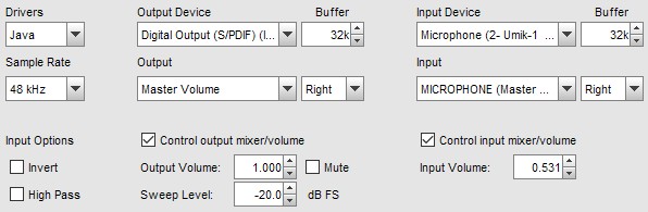
Example Input and Output Settings
Here are some example settings, firstly using Java drivers, a PC's built-in
audio interface and a USB mic. REW has been set to control the levels and the Right
channel is being used for input.
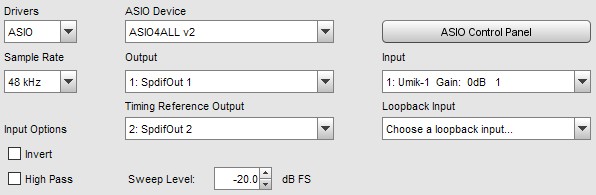
Here are some settings using ASIO drivers, in this case ASIO4All (which
provides an ASIO wrapper around Windows audio drivers). Note that
it is not necessary to select a timing reference output if a timing reference
is not being used. The ASIO Control Panel button launches
the ASIO control panel for the interface.
If the FlexASIO ASIO driver is being used the ASIO Control Panel button
will show a dialog that provides a graphical interface to generate and update the
FlexASIO configuration file, FlexASIO.toml.
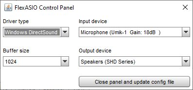
REW's handling of the configuration file only supports the backend
and bufferSizeSamples options. The [input] and [output]
sections will only contain the selected input and output device names, they will
not contain any other options that FlexASIO supports. The configuration file is
updated when the Close panel and update config file button is pressed,
the FlexASIO driver is then reloaded to update the available inputs and outputs.
If the dialog is closed without using the Close panel and update config file
button any changes will be discarded.
Soundcard Calibration File Format
The calibration file is a plain text file which by default has the extension
.cal, though other extensions are also accepted. It should contain the actual
gain (and optionally phase) response of the interface at the frequencies given,
these will then be subtracted from subsequent measurements. The values in the
calibration file can be separated by spaces, tabs or commas.
- Each line of calibration data must have a frequency value and a
gain value, a phase value is optional
- Frequency is in Hz, gain in dB, phase in degrees
- The cal points can be at arbitrary frequency spacing, but each
line must have a higher frequency than the one before and there
must be at least 2 freq, gain data pairs
- Only lines which begin with a number are loaded, others
are ignored
- In comma-delimited files there must be at least one space after the comma
- Spaces before values are ignored
- The sample rate at which the data was generated can be indicated by having
a line which starts "Sample Rate:" (without the quotation marks) followed
by the sample rate in Hz. REW checks for this when loading a file and will
warn if the rate does not match the current interface setting - calibration
data generated at a different sample rate will not provide accurate correction.
Here is an example section of a valid file format:
* Soundcard Calibration data saved by Room EQ Wizard V5.00
* Source: EDIROL UA-1A, Digital Audio Interface, Right channel, volume: no control
* Format:  256k Log Swept Sine, 1 sweep
* Dated: 21-Nov-2010 21:47:56
* Sample Rate: 44100
*
2.019 -1.424 53.471
2.219 -1.238 49.420
2.419 -1.062 45.118
2.619 -0.929 41.888
2.819 -0.823 39.056
3.019 -0.740 36.590
3.219 -0.668 34.409
3.419 -0.607 32.468
3.619 -0.557 30.736
3.819 -0.513 29.177
4.019 -0.475 27.777
4.219 -0.443 26.495
After a calibration file has been loaded it will be applied to all subsequent
measurements. Loading the calibration file does NOT affect any data already
measured and does not affect any measurement data that is imported. The
graph display is updated to show the calibration curve, offset to lie at the
current Target level.
Linear interpolation is used between calibration points. Outside the range of the
calibration data the behaviour depends on whether C weighting compensation has
been selected. If C weighting compensation is selected, C weighting curve figures
will be used for frequencies above or below the range of frequencies in the
calibration data. If not, the calibration values for the lowest frequency in the file
will also be applied for all lower frequencies and the calibration values for the
highest frequency in the file will be applied for all higher frequencies.
The calibration file name and path are remembered for the next startup, the
file will be loaded automatically when REW is started. A message confirming
loading of the file is given.
To stop calibration data being applied, use the Clear Cal... button.
Useful tip: To apply or remove a soundcard calibration file
after a measurement has been taken, simply load or clear the cal data
as required and press the Apply Windows button in the
IR Windows panel to recalculate the frequency response.