REW can make measurements of impedances up to a few hundred ohms by using
both inputs of the soundcard. Impedance measurements of drive units can be used to
calculate the Thiele-Small parameters.
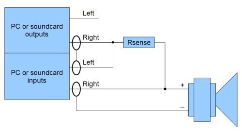
The general connection arrangement for impedance measurements is shown below:
The sense resistor, which must be non-inductive, is used to measure the current flowing into the load, which will be (Vleft - Vright)/Rsense. The sense resistor should have a power rating sufficient to cope with a short circuit load and have a low temperature coefficient. The voltage across the load is Vright, so the impedance is nominally voltage/current = Rsense*Vright/(Vleft - Vright). Note that prior to completing the calibration process the accuracy of impedance measurements is only as good as the accuracy of the value entered for the sense resistor.
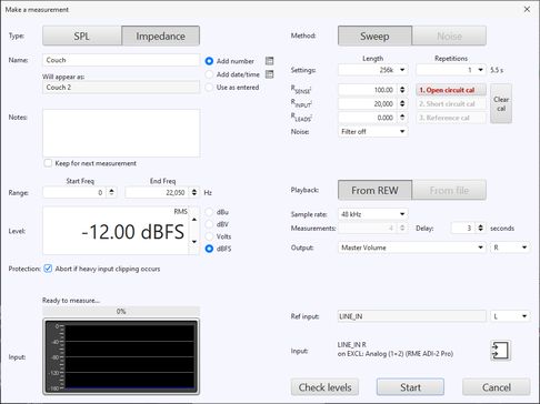
The load appears in parallel with the input impedance of the soundcard and the impedance of the test leads. Before calibration those effects are partially corrected for by using the parallel equivalent of the sense resistor and soundcard input resistance in the calculation, the soundcard input resistance figure is entered on the dialog as RINPUT.
Good results can be obtained using a headphone output (or, even better, a good headphone amplifier or a device with a high power headphone output) to drive the load, with a 100 ohm sense resistor. If a line output is used the sense resistor typically needs to be larger as line outputs have high output impedance and limited drive capability, try 1 kohm but note that the results will have much higher noise levels and be more susceptible to background noise. If the device being used to drive the load can cope with lower loads a lower sense resistor, 47 ohm for example, will improve the results.
An alternative is to drive the load via a power amplifier, which can deliver the lowest noise levels and most accurate results, but great care must be taken as the levels a power amplifier can generate can easily damage soundcard inputs. If using a power amplifier the sense resistor can be much lower, 33 ohms or less, but the soundcard inputs should be connected via a resistive divider providing around 20dB of attenuation and ideally the inputs should also be protected by back-to-back zener diodes to clamp the input to less than 5V.
The soundcard input connected to the load must be the same one which has been chosen as the input in the REW soundcard settings. In the diagram above that is the right input, but if the left is being used simply swap left and right in the diagram. If the left and right connections are the wrong way around the impedance measurements will show curves that are shifted up by approximately the value of the sense resistor.
The input channels should have the same gain. If the audio interface has individual channel gain controls adjust them to have the same gain before starting to measure. An easy way to do that is to connect the impedance rig with the test leads left open and use the signal generator to play a sine tone at 1 kHz at the intended measurement level while observing the input levels on the Level meters. Adjust the input gains so the input and reference channel levels match to within 1 dB and are not clipping.
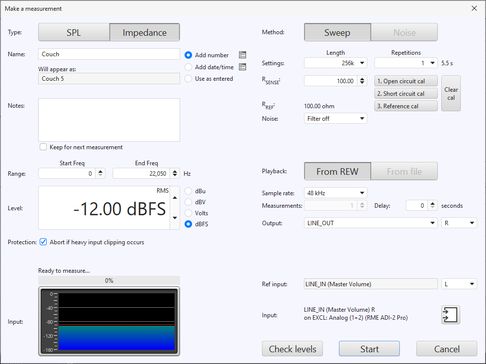
Sweeps of 10 seconds or longer are recommended for impedance measurement to provide good signal to noise ratios in the results.
To get the most accurate results the impedance measurement rig must be calibrated. The calibration can remove the effects of small gain differences between the soundcard input channels, differences in the frequency responses of the channels, and the impedance of the test leads. Three measurements are needed to fully calibrate the rig, but as a minimum the first (open circuit) calibration measurement should be performed. REW automatically saves calibration data from each measurement in the REW log files directory.
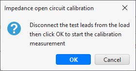
The first step is to calibrate the measurement rig with the test leads open. They should still be connected to the rig, but left open at the load end. This measurement compensates for gain differences between the input channels.
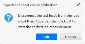
The second step is to calibrate the measurement rig with the test leads shorted. They should still be connected to the rig, but shorted together at the load end. The measurement compensates for the series impedance of the test leads, it particularly improves high frequency accuracy. If this measurement is not carried out the RLEADS box can be used to compensate for the test lead resistance. After this measurement the RLEADS box is hidden since it is no longer used.
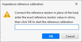
The third and final step is to make a measurement of a known reference resistor. The reference resistor must be non-inductive and its precise value must be known, errors in the reference resistor will translate directly into impedance measurement errors since it is used to scale all subsequent measurements. It should have a value around that of the impedances to be measured, for speaker impedance measurements a reference of 100 ohm or lower is recommended. The reference resistor measurement compensates for frequency response differences between the input channels. It particularly improves accuracy at the frequency extremes. After this measurement the RINPUT box is hidden since it is no longer used.
The calibration data is saved in the REW log files folder and automatically loaded when REW starts up. If the test leads are changed (swapped for longer or shorter leads, for example) or the sample rate is changed the calibration steps should be repeated.
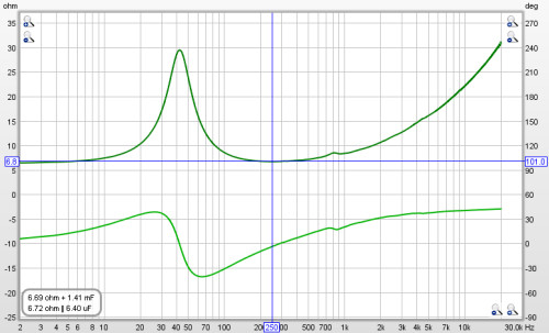
The result of the measurement is displayed in the graph area, information about the measurement appears in the Measurements Panel. Measurements are given a default name of the date and time at which they are made, a more appropriate name can be entered in the box at the top of the measurements panel.
For impedance measurements when the mouse cursor is within the graph panel
the equivalent series resistance + inductance or resistance + capacitance
and parallel resistance||inductance or resistance||capacitance of the impedance
at the cursor position is shown at the bottom left corner
of the graph. This may be useful when making measurements of inductors or
capacitors to check their value, but the
Component Model provides a much more
accurate equivalent circuit.
For details of the various ways of viewing the measured data, including averaging multiple measurements, refer to the Graph Panel help.
If the input channels have been connected the wrong way around the impedance measurements will be too high by approximately the value of the sense resistor, make a test measurement of a resistor (of less than 100 ohms) to check that everything is wired correctly. Swapped channels will also shift the phase by about 180 degrees.
The main source of measurement noise is acoustic noise and vibration during the measurement. Loudspeakers act as microphones, generating small voltages in response to sounds and vibrations that are picked up as part of the load voltage. To minimise this effect use long sweeps, low sense resistor values, avoid noisy environments and isolate the loudspeaker from vibration. Using a power amplifier to drive the speaker provides a much lower drive impedance, which reduces the effect of noise, and allows a low series resistor to be used.
REW provides a Noise filter option which applies a bandpass filter to the captured sweep, synchronised to the sweep frequency, to reduce the influence of noise. The High setting is suitable in most circumstances, but it may have a slight smoothing effect on very sharp resonances. If that is observed try the Medium or Low settings, or turn the filter off. When the filter is being used the sweep duration should be at least 10 seconds, a warning is shown if a shorter sweep is selected. Longer sweeps improve signal to noise ratios in the results with or without the noise filter.